Potentiometer: Arduino Project #2
Goal:
 To control the blinking rate of an LED using the variable resistor called a potentiometer.
Materials:
1 potentiometer
1 LED
1 330ohm resistor
6 wires
Procedure:
1. Assemble the circuit
 potentiometer: a6, a7, and a8 on breadboard
LED: h20 (+) and h21 (-) on breadboard
resistor: i21 and (-) on breadboard
jumper wire 1: e6 and (-) on breadboard
jumper wire 2 :e7 on breadboard and
A0 on Arduino board
jumper wire 3: e8 and (+) on breadboard
jumper wire 4: i20 on breadboard and
Pin 13 on Arduino board
jumper wire 5: (+) on breadboard and
5V on Arduino board
jumper wire 6: (-) on breadboard and
GND on Arduino board
2. Write the code:
3. Upload and test it all:
Circuit and Code Play
Try these on your own before watching the video below for ideas:
1. See what happens if you use two digital pins rather than one digital and one analog pin.
2. See what happens if you use two analog pins rather than one digital and one analog pin.
3. What happens if you replace analogWrite with digitalWrite and vice versa?
Extension Challenge
Again, challenge yourself to see what you come up with before watching the video of what I tried:
1. Can you control 2 lights with the same brightness or same blink rate?
2. Can you control 2 lights with one potentiometer but have them controlled so that as one light gets dim, the other gets bright or one blinks fast while the other blinks slow?
Applications:
I showed my dad my project and he got pretty excited. He was trained in AC repair in the Air Force. He helped me with pronouncing potentiometer correctly and immediately recognized it. He said he used them mostly to control the speed of fans.
 When I taught my youngest son how to change the light in his bedroom (because the fan conflicted with the full-size bunk bed), we noticed a dial you can turn with a screwdriver the globe area to pick what kind of light you want: bright, amber, dim. We're wondering if this is done with a potentiometer.
From the text, these variable resistors are also great for controlling temperature and volume in electronics.
The digital LED built in project #1 has two settings: on and off. These are common in displays such as the monitor light on a CPU to signal it is getting power.
Reflection
 I tried to improve the video quality from project #1: more light, shorter videos for easier uploading to the YouTube channel, setting up the tripod to minimize the camera shake.
I'm hoping next weeks improvements will be to jazz up the layout of the blog a bit. I'm open to suggestions as graphic design isn't my strength but I want to learn.
I was terribly intimidated by such a small circular object. But it turns out potentiometers are both easy and useful. I struggled with the extension challenge a bit, but I gave it a good try. I think I'm missing something basic. I don't think I completely understand parallel and series circuits. In this project, I put the two LEDs in the same lines. I rewatched our professor's video and he staggered his LEDs. As I understand it, series circuits feed into each other, so if you remove one the other will go out as well. Parallel circuits operate independently of each other.
Even though I didn't figure it all out, I'm glad I tried. It will mean so much more when I do more research and discuss with my peers. As my youngest said earlier, "If you're not failing, you're not learning.?
 To control the blinking rate of an LED using the variable resistor called a potentiometer.
Materials:
1 potentiometer
1 LED
1 330ohm resistor
6 wires
Procedure:
1. Assemble the circuit

LED: h20 (+) and h21 (-) on breadboard
resistor: i21 and (-) on breadboard
jumper wire 1: e6 and (-) on breadboard
jumper wire 2 :e7 on breadboard and
A0 on Arduino board
jumper wire 3: e8 and (+) on breadboard
jumper wire 4: i20 on breadboard and
Pin 13 on Arduino board
jumper wire 5: (+) on breadboard and
5V on Arduino board
jumper wire 6: (-) on breadboard and
GND on Arduino board
2. Write the code:
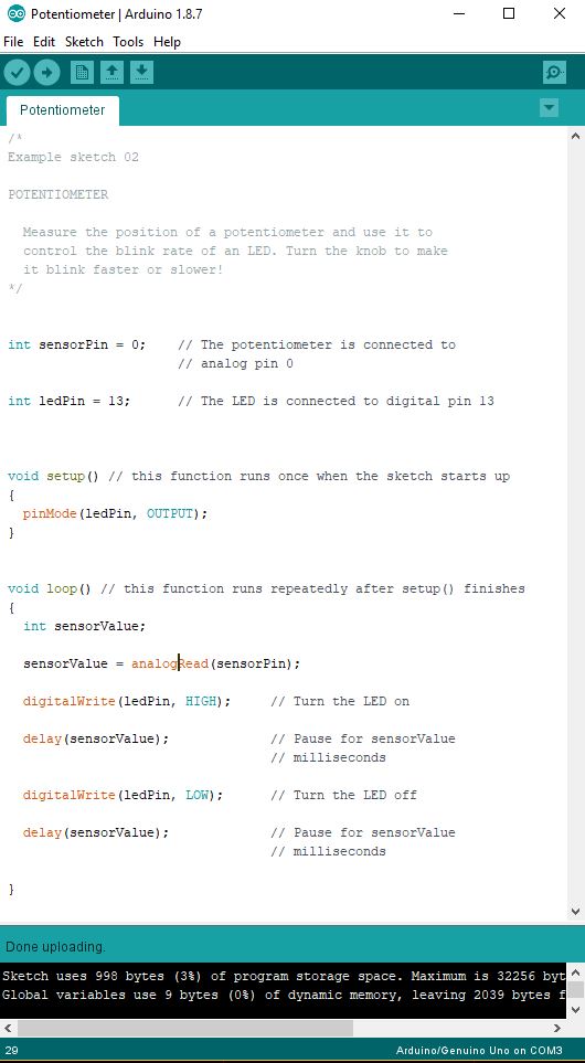 |
| IDE code for Arduino Board |
 |
| Electronic Diagram |
3. Upload and test it all:
Circuit and Code Play
 |
| Don't forget to change the code to reflect the pin change |
1. See what happens if you use two digital pins rather than one digital and one analog pin.
 |
| More code changes with pin changes |
2. See what happens if you use two analog pins rather than one digital and one analog pin.
3. What happens if you replace analogWrite with digitalWrite and vice versa?
Extension Challenge
 |
| Is it still a series circuit if one stays lit when I remove the other? |
1. Can you control 2 lights with the same brightness or same blink rate?
2. Can you control 2 lights with one potentiometer but have them controlled so that as one light gets dim, the other gets bright or one blinks fast while the other blinks slow?
 |
| Jumping from one end of the potentiometer |
 |
| Jumping from the other end |
Are there considered
parallel circuits?
Applications:
I showed my dad my project and he got pretty excited. He was trained in AC repair in the Air Force. He helped me with pronouncing potentiometer correctly and immediately recognized it. He said he used them mostly to control the speed of fans.
 When I taught my youngest son how to change the light in his bedroom (because the fan conflicted with the full-size bunk bed), we noticed a dial you can turn with a screwdriver the globe area to pick what kind of light you want: bright, amber, dim. We're wondering if this is done with a potentiometer.
From the text, these variable resistors are also great for controlling temperature and volume in electronics.
The digital LED built in project #1 has two settings: on and off. These are common in displays such as the monitor light on a CPU to signal it is getting power.
Reflection
 I tried to improve the video quality from project #1: more light, shorter videos for easier uploading to the YouTube channel, setting up the tripod to minimize the camera shake.
I'm hoping next weeks improvements will be to jazz up the layout of the blog a bit. I'm open to suggestions as graphic design isn't my strength but I want to learn.
I was terribly intimidated by such a small circular object. But it turns out potentiometers are both easy and useful. I struggled with the extension challenge a bit, but I gave it a good try. I think I'm missing something basic. I don't think I completely understand parallel and series circuits. In this project, I put the two LEDs in the same lines. I rewatched our professor's video and he staggered his LEDs. As I understand it, series circuits feed into each other, so if you remove one the other will go out as well. Parallel circuits operate independently of each other.
Even though I didn't figure it all out, I'm glad I tried. It will mean so much more when I do more research and discuss with my peers. As my youngest said earlier, "If you're not failing, you're not learning.?

Comments
Post a Comment